Chip Formation in metal cutting | Explained
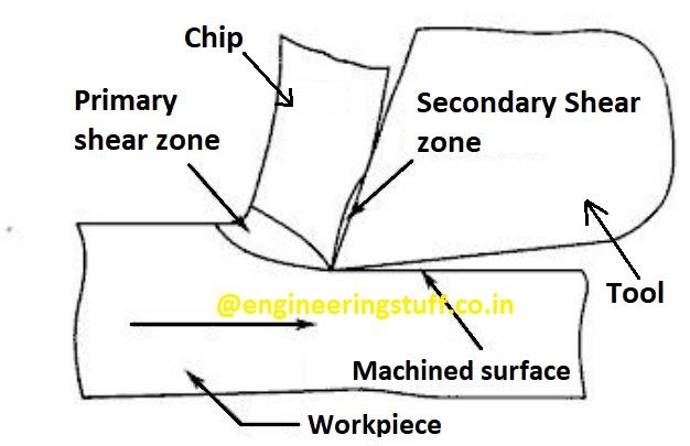
One of the most challenging procedures is metal cutting. With first an elastic and subsequently a plastic compression, the metal directly in front of the tool rake face is shaped. Given that material in the final form is separated from the parent metal by shearing, this area is referred to as the “shear region” in traditional usage. Depending on the cutting conditions, a yield or fracture marks the beginning of the real separation of the metal, beginning at the cutting tool’s tip.The chip of distorted metal then spreads across the tool’s face. The chip can undergo secondary deformation, which occurs when there is sufficient friction between the tool rake face and the bottom (deformed material) of the chip. Chip curl refers to the curve that results when the chip is moved away from the tool after sliding over the tool rake face.
Yielding, in which strained layers of material are pushed onto other layers along the slip-plane, which coincides with the direction of highest shear stress, can result in plastic deformation.
The chip’s size and shape can vary during actual manufacturing. One of the most crucial aspects of metal cutting is chip examination. The physics of metal cutting are highly reliant on the size and shape of the chips generated, as will be evident later.
There are three general categories for chip creation in metal cutting:
(i) Discontinuous chip
(ii) Continuous chip, and
(iii) Continuous chip with BUE
Discontinuous Chip:
When a brittle substance, like cast iron, is cut, the deformed material breaks relatively quickly, producing a chip made up of broken pieces. In this kind, the distorted material occasionally bursts rather than flowing constantly. In terms of chip disposal, discontinuous chips are simpler. However, as the fracturing cycle changes, the cutting force becomes unstable
Furthermore, they typically offer a higher surface polish. However, they result in poor surface polish and shorter tool life when used with ductile materials. discontinuous chips are more likely to be produced by deeper cuts (higher chip thickness), slower cutting speeds, and smaller rake angles.
Continuous chip:
Steel or ductile metals are typically machined at high cutting rates, which typically results in continuous chips. The continuous chip, which flows over the rake face like a ribbon, is continuous. Due to the metal’s ductility (steel at high temperatures produced by cutting), which flows along the shear plane rather than breaking, continuous chipping is possible. A continuous chip lacks notches as a result. Each layer of metal is expected to flow along the slip plane until work hardening causes it to halt. All of these layers come together.
The prior ones become weldable at the higher temperature, creating a continuous chip. Sharp cutting edges, small chip thicknesses (fine feed), broad rake angles, rapid cutting speeds, ductile work materials and effective lubrication are a few perfect circumstances that encourage continuous chipping in metal cutting.
This type of chip is the most preferable since it cuts smoothly and produces a nice surface quality. It also contributes to reduced power usage and longer tool life. However, chip disposal is a challenge because of the enormous coils of chips. To help in this regard, a variety of chip breakers in the shape of steps or grooves on the tool rake face have been devised. Chip breakers enable the breaking of chips into smaller pieces for easier disposal.
Continuous Chip with BUE:
Some chip particles stick to the tool rake face close to the tool tip when the friction between tool and chip is significant during cutting ductile material. When such a big amount of material is stacked up on the rake face, it substitutes for the actual cutting edge and acts as a cutting edge. The built up edge is what it is termed (BUE). BUE is harder than the original work material in terms of hardness.
As the BUE gets bigger, it becomes unstable and when it’s cut, parts begin flying out. The removed parts of the BUE are partially attached to the chip’s machined surface and partially to the chip’s underside. A rough completed surface is the end result. However, since the BUE performs the cutting operation rather than the actual tool tip, the BUE increases the life of the cutting tool. Therefore, using BUE during rough machining is safe.
Low cutting speed, high feed, and low rake angle are the circumstances that frequently lead to the production of BUE. The material of the work piece must undergo work hardening as it is one of the conditions for BUE formation. The surface of the machined object is rougher if higher is the work hardness.
Although the aforementioned is a hypothetical classification of chips, there will actually be a large number of additional varieties that can be found in these three types’ boundary regions.


