Sliding mesh Gear box | Components, construction and working
Sliding mesh is conventional type of gear box and is first type of gear box invented for a automobile. First gear box having 3 speed gear ratio was invented by French engineers called Louis and Emile. In this type of gear box as name suggests has gears sliding upon a shaft and makes engagement with gears of mating shaft.
Components of Sliding mesh gear box:
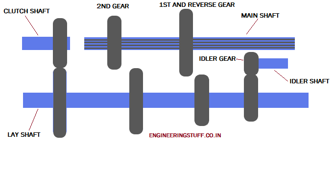
Sliding mesh gear box has same set of shafts like we have in our modern constant and synchromesh gear box i.e. Clutch shaft , Layshaft (Counter shaft) and main shaft, one addition in few settings of gear box is the idler gear mounting shaft for reverse. Spur gear is the only type of gear which can be used in sliding type gear box because axially parallel meshing of gears is required to happen. Other than these Shifter forks, Fork guide shaft, gear linkages and gear lever are part of gear box.
Construction:
Power from engine is received in gear box through clutch shaft. Clutch shaft has a fixed gear in constant meshing with a gear, fixed on lay shaft. Clutch shaft has gear train with different size of gears having fixed positions upon shaft and in continuous rotation with lay shaft. Another gear train is fitted on main shaft, this shaft is splined through out its length and gear of different sizes mounted upon it are in continuous rotation with shaft and also can slide axially upon this shaft. One more shaft having reverse idler gear is placed between lay shaft and main shaft. Shifter forks guided on shafts are placed at grooves of gears for sliding gears on main shaft, movement of shifter fork is made possible by linking it to gear lever. main shaft takes off output power of gear box.
Working:
Working of Sliding mesh gear box is very simple. It can be easily understood by above layout, This layout shows arrangement of 3 speed sliding mesh gear box.
Neutral position:
In above layout gear box is in neutral position i.e. power coming from clutch shaft is not transferring to main shaft and further. Contact is breaking between main shaft and layshaft.
1st Gear:
Move 1st and reverse gear to its right and engage with very next gear of layshaft. This arrangement is set for 1st gear.
Reverse Gear:
Move 1st and reverse gear towards reverse idler gear and engage with idler gear. Idler gear in layout looks very near to main shaft gear but it is offset backwards. this arrangement is set for reverse gear.
2nd Gear:
Move 2nd gear of main shaft to its right and engage it with very next gear of layshaft. This arrangement is set for 2nd gear.
It looks clear from layout that in 1st gear driver gear is smaller than driven gear and hence transmits higher torque and less speed. For reverse gear, idler changes rotation direction of main shaft and provide reverse direction to vehicle.
In 2nd gear arrangement driver gear is bigger than driven gear and thus reduces torque and provide high speed to vehicle.
This layout is a basic arrangement of gears for understanding. This arrangement is complex for gear boxes having number of gear ratios more than 3 and also set up may differ from above layout.