Fatigue analysis | Engine development and production
The topic of processes that properly define the endurance of an engine starts with fatigue. For several engine parts, it is the main failure cause and the target of the largest fraction of the research and tests to which most engines and engine components are subjected. This section gives only a short summary of the science of fatigue, demonstrating its relevance to the production of engines.
The tension is the ratio between the change in length and the bar’s original length, and the stress is the tensile or compressive load added per unit area. As long as the load applied per unit area is below the material’s yield power, when the load is withdrawn, the bar will revert to its original length, matching the linear part of the material. The deformation occurring under these conditions with load is known as elastic deformation.
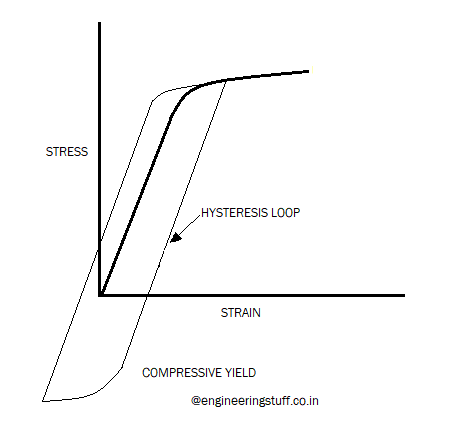
The bar will be forever deformed when the yield force is surpassed. The bar returns to a parallel line, such as the illustration of the dotted lines seen in the diagram, if the load is now removed. The bar hits zero when the load reaches at a longer, deformed duration, it persists. Plastic deformation has arisen from the loading. Also seen is a related loading excursion by compressive yield.
The slope of the plot’s elastic (linear) component gives a measure of the material’s elasticity. Materials with higher elasticity, and thus a shallower slope, would have greater deflection per unit load. The elasticity modulus is the stress to strain ratio, which is thus the normal elasticity metric. The difference in strain between that at the yield strength of the material and that at its final strength determines the material’s ductility.
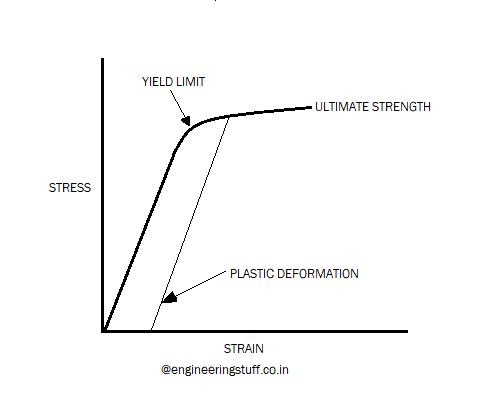
Until fracture, a brittle material will elongate very slightly, whereas a ductile material will exhibit substantial elongation. The normal sign norm is that positive values are given to tensile stress and strain, and negative values are given to compressive stress and strain. Compressive loading can also be used in the discussion of engine elements.
It will inevitably crack when a substance is continuously loaded and unloaded, even though the loading is far below the ultimate power. While it will take several more cycles, it will also fracture well below the yield strength under cyclic loading. Such fractures are referred to and are the subject of this section, as fatigue fractures.
Usually, the figure shown is called an S-N diagram, where ‘S’ is the alternating cyclic stress around a mean of zero in either direction, and ‘N is the number of cycles resulting in a fracture. The alternating stress remains slightly below the yield strength of the material at the right portion of the figure, and the loading remains fully elastic. In this section of the figure, an endurance limit is defined. The endurance limit is also defined as an alternating stress magnitude when dealing with ferrous materials which if not exceeded results in infinite life.
This terminology remains disputed, although some fatigue specialists will argue that if adequate loops are applied, even at alternating stress thresholds below the durability limit, a fracture will still be observed. The ideas of an endurance limit and eternal life from a realistic point of view remain important as the alternating tension must be held below that which will result in loss over the life of the product.
For instance, over a useful life that requires its use of two or three rebuilds, a crankshaft can basically be subjected to 3 billion alternating load cycles. And if the crankshaft had failed to reach its endurance limit if subject to 10 billion alternating load cycles for all practical purposes and thus it was devised for infinite existence.
The S-N diagram does not level out in the case of non-ferrous materials, since the alternating load is decreased and the durability principle cannot be implemented. In Figure , the material can crack under less stress cycles as the alternating load is intensified. If the curve is traversed toward the left it deviates from the purely elastic loading line as the substance starts to yield, and plastically distort. As seen in the inset stress-strain diagram, the load cycle appears. When the yield point is first crossed, the load is referred to as dominated by strength. With each load loop, further alternating load increases result in greater plastic deformation.
This is further depicted in the ductility-dominated loading called stress strain inset. The fatigue loading area important to the production of most engine components is solely elastic loading. As a result of high thermal heating, a few parts, such as the cylinder head fire deck and exhaust manifolds, can undergo some plastic deformation, but even these remain in the prevailing strength regime.
The obtaining of exact fatigue properties for the material being used is one of the first problems of fatigue research. Many materials are not well defined, and substantial heterogeneity is present also in those that have been thoroughly tested, such as gray iron and different aluminum alloys.
One reason for this inconsistency can be found in the fact that the reaction of the material to fatigue loading depends not just on the composition of the metal, but also on the processing to which the material was subjected and the microstructure resulting from it. For geometrically complex castings and forgings, this implies that within a given section, the fatigue properties can differ even from one area to another.
That of temperature is another significant variable. The fatigue strength is heavily temperature dependent, especially in the case of aluminum alloys, and this must be taken into account in the study.
The fatigue power of a full-load working crown aluminum piston is on the order of half that of at ambient temperature . It is recommended, wherever possible, that fatigue samples be taken from separate regions of interest in the sample components and that fatigue data (S-N diagram) be produced as part of the analysis process.
To better simulate the kinds of pressures that would be seen by the component being studied, the fatigue test should be selected. For example, if a cylinder head is being analyzed and the engineer is particularly concerned about the fatigue life in the regions of the valve bridge, test specimens should be taken from the head casting valve bridges (or equivalent casting using the same alloy and casting method in the case of a new design).


