DC motor |What is DC motor |How DC motor works
Construction of DC motor
In constructional features, conventional DC motors closely resemble DC generators. However, by appearance alone it is hard to identify them. The motor consists of the same two main parts as the generator— the arrangement of the field and the armature consisting of the armature core, armature winding, commutator, and brushes.
The Field structure: There are at least two pairs of field poles in the field configuration of the motor, but there are also four-pair motors. The field windings of the individual field poles provide a strong magnetic field. The magnetic polarity of the field system is arranged so that the polarity of any particular field pole is opposite to that of the poles adjacent to it.
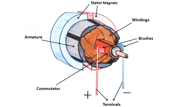
The armature: A cylindrical iron frame connected directly to the motor shaft is the motor armature. The rotating part of the motor is the armature in a DC motor. The winding’s of armatures are inserted into the slots on the armature surface and terminate in parts of the commutator. Current is fed to these winding’s on the rotating armature by carbon brushes that press against the commutator segments.
This current in the winding of the armature produces a magnetic field in the armature interacting with the magnetic field of the field poles. Such magnetic fields are used to produce a torque that twists the armature. The commutator shifts the path of the current in the armature conductors when they travel between poles of opposing magnetic polarity. These reversals in the armature current lead to the continuous rotation in one direction.
Through following the right-hand rule for the motors, you can decide which way the current-carrying conductor should travel when put in a magnetic field. This is the concept of all motor action. The first finger is the position of the stator flux as the magnetic lines travel north to the south. The middle finger indicates the direction of the electron current in the conductor located within the magnetic field. The thumb reflects the conductor’s movement as it tries to move out of the magnetic field.
Type of DC motors:
Different types of motor like Shunt, series, compound, and permanent magnet motors are all widely used. The type of motor to be used is chosen according to the technical specifications of the required load. A shunt motor has a field circuit attached in a shunt (parallel) to the armature, while a series motor has a system of armature and field circuits. In compound motor both series and shunt field windings are present. In permanent magnet motor only armature connections are their.
Torque :
The rotating force on the motor shaft is called a torque, which is produced by the contact between the magnetic fields of the armature and field poles. As the twisting force of the shaft increases, the magnitude of shaft torque increases. Torque shall be specified as the force in pounds and the radius of the shaft or pulley in the feet.
The torque in the motor relies on the magnetic power of the field and the armature. strength of the armature magnetic field increases. The torque decreases along with the armature current while The torque increases along with the armature current.
Motor rating:
The number and attachment methods for the armature and field determine the operating characteristics of the motor. The voltage, current, speed and horsepower output of DC motors are measured.
Rotation:
Direction of field circuit and the armature circuit defines the direction of armature rotation of DC motor. If the rotating direction is to be changed, the present position in either the field or the armature must be reversed. The reversing of the power supply contributes to the reversal of both the armature and the field Use the right-hand law for motors to determine the direction of the conductor’s movement
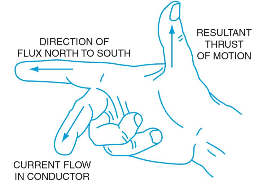
The thumb indicates the direction of the resulting thrust. The first finger shows the direction of the flux (north to south), the middle finger indicates the direction of the current flow (negative to positive).
Starting current and CEMF:
The DC motor starts with a much higher current than the current while the motor runs at its rated speed. Once instant power is applied, the armature becomes motionless and the armature current is restricted only by the extremely low resistance of the armature circuit wire. when motor builds up its speed, the input of the current reduces till the motor reaches its rated speed. At this stage, the current of the armature stops decreasing and remains constant.
The voltage generated within a rotating armature depends on the rotation speed and magnetic field strength. As in any generator, the left-hand rule applies here. Even though the armature is induced to rotate by motor motion, the process of rotating a wire coil within a magnetic field allows it to behave as a generator.The thumb is the direction of the traveling conductor’s drive, and the first finger is the direction of the main magnetic flux stator field The first finger also indicates the path of the induced current flow within the armature conductors, which is in comparison to the current applied.This counter induced potential is CEMF.
Here the induced current flow is lower in magnitude than the applied current flow from the source of the voltage. The difference between the current flow introduced and the counter-induced current is the differential current.
As the torque or spinning force rotates the armature,the conductors of the armature cut the main field magnetic flux, as in a generator . This behavior causes a voltage in the winding of the armature that contradicts the line voltage.
The CEMF produce in a DC motor allows for shifts in current at different speeds to a motor armature. When there is no current in the circuit, the motor armature becomes motionless and the CEMF becomes zero. The beginning current is very strong, because only the ohm resistance of the armature restricts the current.
As the armature continues to rotate the CEMF rises and the line current reduces.The value of the CEMF exceeds the value of the applied voltage when the speed starts increasing but is never equivalent to it. The voltage value that directly pushes the current through the motor is proportional to the difference between the voltage applied and the CEMF. At regulated rpm, this variation in voltage just maintains the motor at constant speed.
The speed and CEMF decrease when a mechanical load is applied to the motor shaft. Moreover, the variation in voltage rises and triggers the motor to boost input speed. Every further increase in mechanical load results in a proportional increase in input current
As torque depends on the strength of the magnetic field of the armature, depending on the current of the armature, any change in mechanical loads requires an increase in the current of the armature, more loading, slower velocity, higher differential, and more current.


Recent Comments